ME35: RObotics
Image from: https://www.theverge.com/2019/4/2/18292326/lego-spike-prime-programming-bricks-scratch-technic-robotics
Robotics documentation
Each project has a corresponding heading and write-up
Lego BRick CAD
To the right is my lego brick. It is made in OnShape and can be accessed at this link.


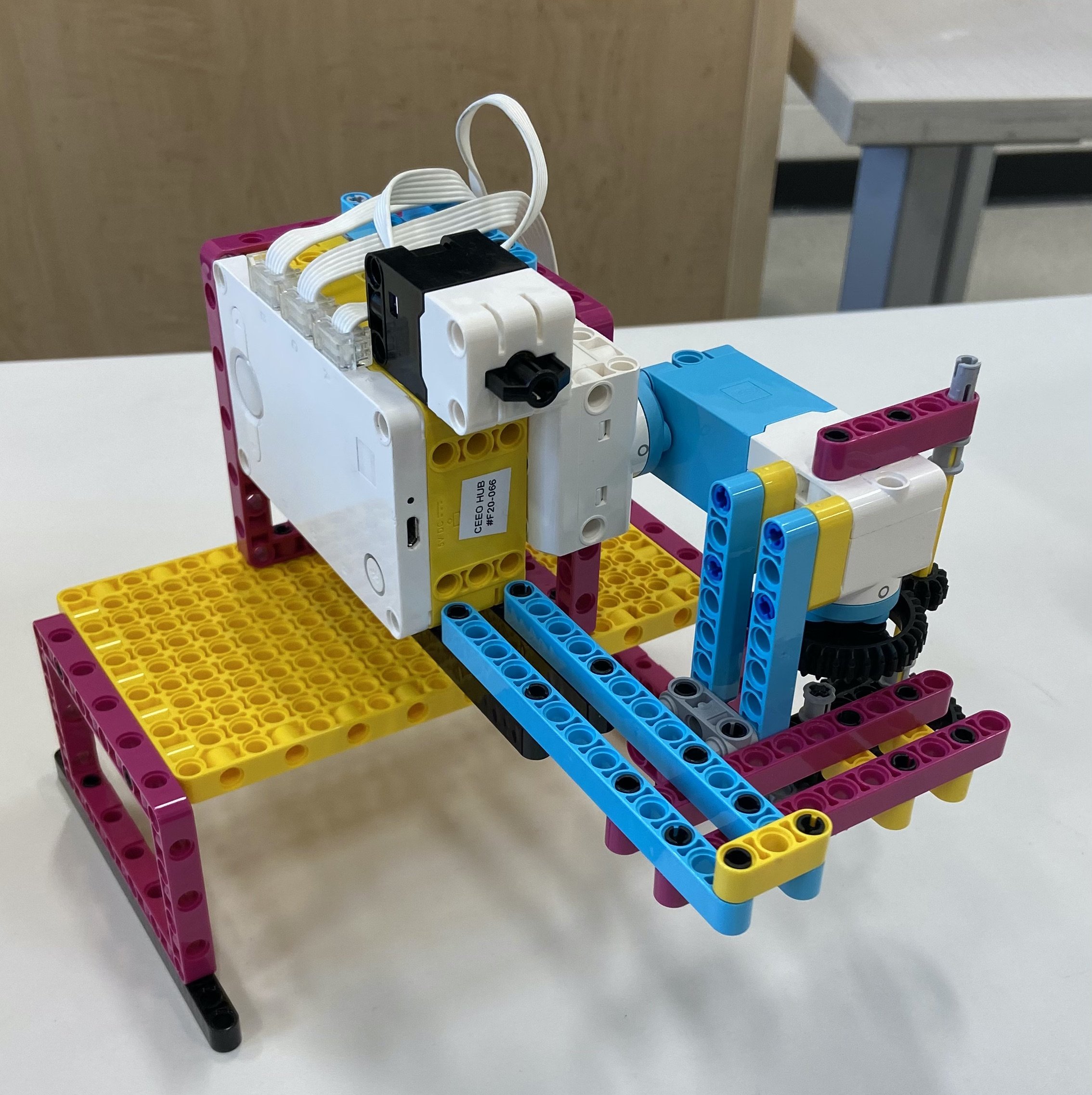
Top Spinner robot

Our top with some prototype parts to its left.
My partner Jake and I built a robot with a 1:25 gear ratio that would spin up a top that we fabricated ourselves. Our robot slowly spools up the top until it is at maximum velocity, at which point it alerts you to push a button that releases the gears from the top, allowing you to remove the device and leave the top spinning. We built our top out of laser cut acrylic, a wooden dowel, imperial screws and nuts, and 3D printed parts. Our longest spin went for 43 seconds!

Our device releases the top by pulling the gears away at the push of a button
Our spike prime spinning mechanism
Line following robot
For this project, we were tasked with building a spike robot that could follow black lines, stop when it saw yellow lines, and turn onto red lines. Our robot would also need an ultrasonic sensor detection system that would avoid obstacles.
My partner Shawn and I began to tackle the simplest part of the assignment: line following. We designed a proportional controller based on luminosity readings from a color sensor. The robot could calibrate itself by reading the white and black luminosity values, and then creating an offset between them to follow. This method worked very well after we tuned the gains.
We used the color sensor to detect the colored lines. Our whole robot was controlled by a main loop with a state machine case structure. Depending on the ultrasonic sensor, color sensor, and luminosity readings, our robot would enter into different “states” which would change its behavior. This made it easy to seamlessly integrate obstacle avoidance, line following, and color sensing.
This project was a great exercise in proportional control theory and state machines!

Testing the pressure plate mechanism
Dog Feeding Robot
For this project, my team of two other students and I were tasked with building a robot that would dispense food to our professors dog Nellie after the dog interacted with our robot. We had to make sure the robot was food safe, free of sharp parts, and simple enough that a dog could be trained to use it to get food.
We decided to have our method of interaction be a large pressure plate. When prototyping the pressure plate, we made sure that it could be triggered with a push anywhere on its surface, making it easier for a dog to trigger.
We then built a dosing system using a food-safe funnel. A motor positioned inside the funnel would stir the dog food and it would trickle through the funnel and out onto the pressure plate.
Finally, we coded an algorithm that would sense changes in the pressure plate and “add points” to a tally that would keep track of how much the dog interacted with the dispenser. When the points reached a certain threshold, the dispenser would release food. We also hard coded a “food dispense maximum” that would prevent the dog from eating too quickly.
Our testing with Nellie showed promise, as she was able to press the pressure plate and dispense food. Unfortunately she broke the device on her first try.

Interacting with the pressure plate causes food to come out of the dispenser

Nellie plays with our food dispenser. She broke the pressure plate on her first try, but still got food to come out.

Our advert for the “Pupper Plate”
Project 4: Data Dashboard
Project 5: Toothpaste dispenser
Project 6: Pick a processor

I was given the Adafruit Circuit Playground Express to experiment with. I decided to program a game in CircuitPython that would use the accelerometer and LED array. It was fairly simple to implement and the code is located here.
Final project: Cake baking + Frosting system
We’re building a cake baking + frosting system that will be able to mix cake batter, bake a cake in an oven, and frost an image onto it. I’m part of the frosting mechanism team, which aims to build a mechanical frosting system that is capable of drawing a 2 color image onto a cake. We plan on building a robot that can move in cartesian space on a set of aluminum 2020 rails. Frosting will be extruded via syringe, routed through a tube to the end effector of the robot. A system diagram of the whole project is below.
Edit 4/28: Full Documentation of Final Project!
