Spring constant design project

The stress plot of our final design in Solidworks showed that there were small areas of yielding. It also showed that we had done a good job of removing mass in areas of low stress.
Project description

We tried out many different ideas before settling on the shape pictured above. It was defined by a few critical dimensions, like the distance from the bend to the applied load.
In my engineering design II class, our first project was to create a water-jet, 0.25” thick, aluminum member that would deflect 0.5” under a 200lb load without yielding. Essentially, we needed to design a spring with a spring constant of 400lb/in.
We were placed into groups of five and we were given drawings of the constraints of the project. There was to be a 200lb force offset three inches from two supporting pins. This posed a great challenge, because we needed to achieve a large deflection without yielding.
Our group of five started by doing a basic back-of-the-envelope Castigliano analysis to determine a general size for the load-bearing arm of our member. We began iterating through different designs in Solidworks, fielding design ideas from the team and running FEA simulations to determine whether the idea was worth pursuing.
I encouraged our group to try as many ideas as possible, before we settled on a C-shape with tapering arms. After selecting this promising shape, we made its critical dimensions drive other dimensions in the shape so that we could quickly vary the proportions of the model and see if it improved our results.

We did a simple Castigliano analysis to ensure that our simulated results were on the right order of magnitude.
Once we had a good model, we used the Solidworks iso plot feature to begin looking at how we could optimize our design. Teams with lighter designs would score higher on the project, so we really tried to remove as much material as possible without compromising functionality.
Finally, we had our design tested on an Instron machine, and it performed very well. It achieved a spring constant of 444 lb/in and deflected 0.465” under the 200lb load, with minimal yielding.
Our design was one of the lightest designs to achieve a reasonable spring constant with minimal yielding, so we were really satisfied with the result. Through this project, I learned more about working constructively with a team of four other engineers through a virtual platform.
The full report is embedded at the bottom of the page.
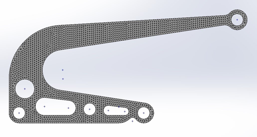
We used Solidworks FEA to quickly check our deflection results.

Our max predicted deflection was 0.475”. The actual deflection of our model was 0.465”.

The results of our Instron test were promising. We achieved a spring constant of 444 lb/in with minimal yielding (shown in blue).
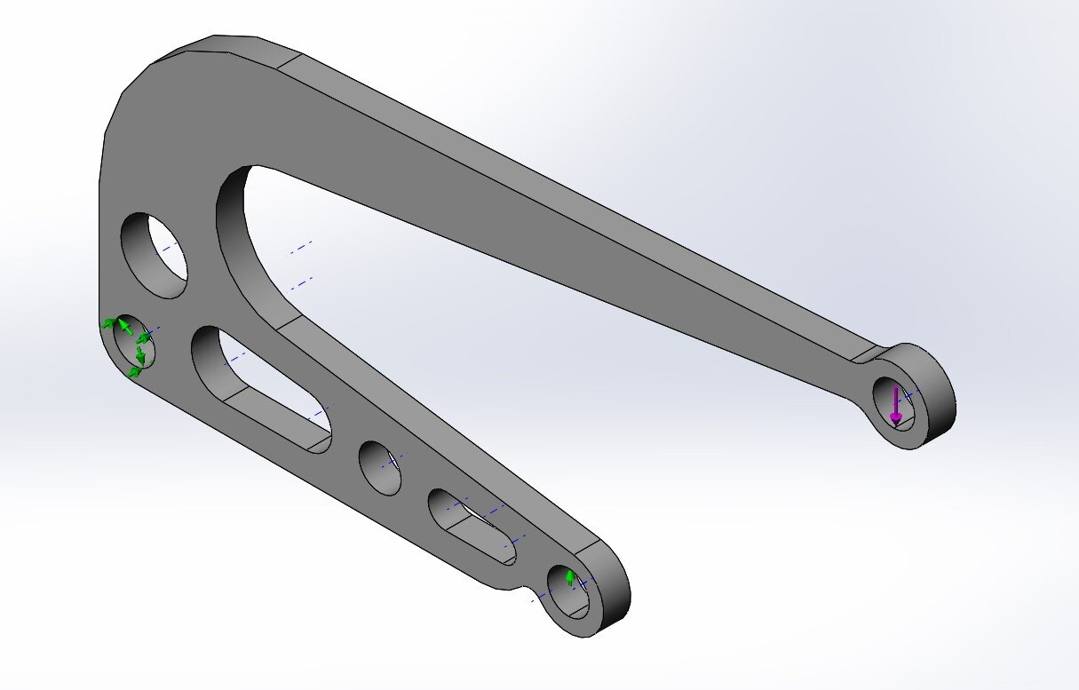
The model was constrained by two pins at the bottom, and the load was applied in the top right corner, offset from the bottom pins.
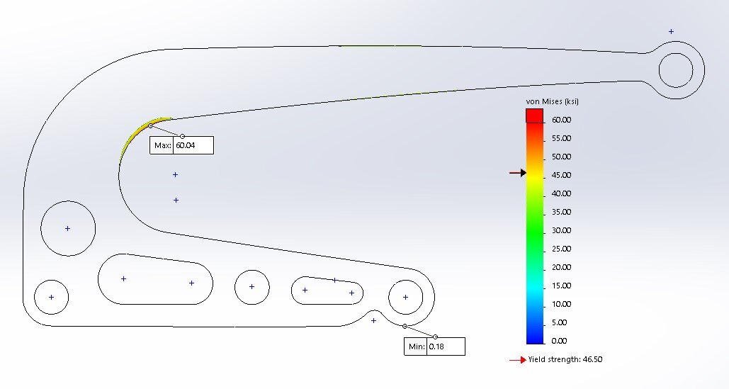
This image shows the small regions of predicted yielding in our model. We considered these regions to be small enough to be acceptable for the purposes of this project.