3D printeR ENclosure

A concept render of the enclosure that I created in SolidWorks
Project Description
Looking to keep myself busy during the Covid-19 pandemic, I decided to build an enclosure for my 3D printer similar to this one on Instructables. I wanted the enclosure to encapsulate my 3D printer and all its accessories (including Raspberry Pi and control box). It needed to be sturdy, affordable, and easy to assemble and disassemble.
I started by building a CAD model and a bill of materials, so that I could plan out how I would acquire the materials, cut down the stock, and assemble the enclosure, using only the hand tools I had available at home. I designed the enclosure to be built out of two Walmart Mainstays Bedside Tables, as the Ikea Lack Tables recommended in the Instructables were unavailable due to the pandemic.
These tables were attached with 3D printed friction fit leg mounts and 3 MDF panels were cut and mounted in the spaces between the tables using L brackets. Sound-insulating foam squares were glued to the MDF panels to dampen the printer’s noise. A hole was drilled through the top table for filament, and 3D printed brackets were mounted to the bottom to hold the control box, Raspberry Pi, and power strip. LED strips were cut and soldered together to provide interior lighting. Finally, an acrylic sheet was cut and mounted to two hinges where it would line up with 3D printed magnet holders to act as a door to the enclosure.
The whole project cost less than 150 dollars and was completed in two weeks. It quieted the 3D printer by 10dB and improved print quality thanks to the sturdy frame and warm printing environment. This was a great project to keep me actively designing and building even when I did not have access to a makerspace.
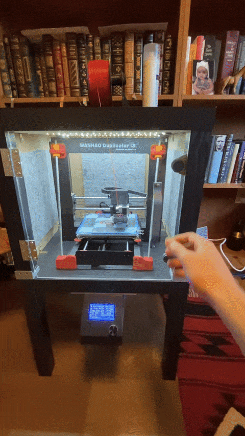
The acrylic door on the front of the enclosure is magnetic and has an ergonomic 3D printed handle

The enclosure shortly after finishing the installation of the MDF panels. At my parents house I only had access to hacksaws to cut the fiberboard.

The finished enclosure included a power strip with individual switches (on the right), sound-insulating foam, and mounting brackets for the control box and Raspberry Pi.

LED strips were cut to size, soldered together, and then glued to the roof of the enclosure to provide interior lighting.

The entire enclosure was modeled in SolidWorks, so that I could do fit checks and test ideas in the virtual world before fabricating it in real life.

I made sure to create a BOM as I designed the enclosure so that I could keep track of where I would buy the materials and how much I was spending on the entire project.